Communication protocols
The four frame formats the TMC9660 speaks (bootloader and TMCL, over SPI and UART), byte by byte, with their checksums.
You need this page to write a protocol analyser decoder or to debug a port at the wire level; the driver builds and checks every frame for you.
Protocol Overview
The TMC9660 supports two communication interfaces: - SPI: Full-duplex, high-speed, delayed replies - UART: Half-duplex, command/reply order, autobaud support
Each interface has two protocols: - Bootloader Protocol: 5-byte frames (40 bits) for SPI, 8-byte for UART - Parameter Mode Protocol (TMCL): 8-byte frames (64 bits) for SPI, 9-byte for UART
Bootloader Protocol
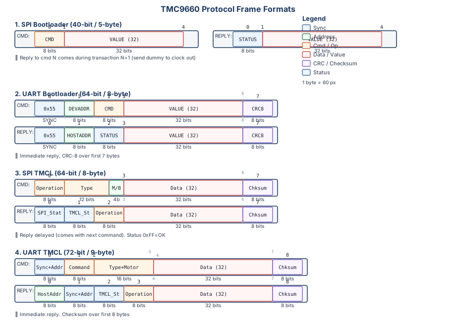
SPI Bootloader Protocol (40-bit / 5-byte)
Transaction 1: SEND COMMAND
┌──────────┬──────────────────────────────────────────┐
│ TX (5B)  │ [CMD] [VALUE(32)]                        │
│ RX (5B)  │ [PREV_STATUS] [PREV_VALUE(32)]           │
└──────────┴──────────────────────────────────────────┘
                    ↓
Transaction 2: RECEIVE REPLY
┌──────────┬──────────────────────────────────────────┐
│ TX (5B)  │ [NO_OP] [0x00] [0x00] [0x00] [0x00]      │
│ RX (5B)  │ [STATUS] [VALUE(32)]                     │
└──────────┴──────────────────────────────────────────┘
Key Features: - Frame Size: 5 bytes (40 bits) - No Bit-Flipping: Data sent and received as-is - Reply Delay: Reply to command N comes during transaction N+1 - Dummy Frame: Send all zeros to clock out reply
UART Bootloader Protocol (64-bit / 8-byte)
COMMAND FRAME (8 bytes):
┌────┬────┬────┬────────────────────────┬────┐
│0x55│DEVA│CMD │    VALUE (32-bit)      │CRC8│
│    │DDR │    │   [MSB ... ... LSB]    │    │
└────┴────┴────┴────────────────────────┴────┘
 Sync  Dev  Cmd    Byte3 Byte2 Byte1 Byte0  Checksum

REPLY FRAME (8 bytes):
┌────┬────┬────┬────────────────────────┬────┐
│0x55│HOST│STAT│    VALUE (32-bit)      │CRC8│
│    │ADDR│US  │   [MSB ... ... LSB]    │    │
└────┴────┴────┴────────────────────────┴────┘
 Sync  Host Stat   Byte3 Byte2 Byte1 Byte0  Checksum
Key Features: - Frame Size: 8 bytes (64 bits) - No Bit-Flipping: Bytes transmitted as-is - Immediate Reply: Reply comes immediately (no dummy frame needed) - CRC-8 Protection: Polynomial x⁸+x²+x¹+x⁰ over first 7 bytes - Addressing: Device address (default 1) and Host address (default 255)
Parameter Mode (TMCL) Protocol
SPI TMCL Protocol (64-bit / 8-byte)
Command Format:
┌──────┬──────────┬──────────┬──────────────┬──────────┐
│ Byte │ 0        │ 1-2      │ 3            │ 4-6      │ 7        │
├──────┼──────────┼──────────┼──────────────┼──────────┼──────────┤
│ Bits │ 0-7      │ 8-19     │ 20-23        │ 24-55     │ 56-63    │
│ Desc │ Operation│ Type     │ Motor/Bank   │ Data      │ Checksum │
└──────┴──────────┴──────────┴──────────────┴──────────┴──────────┘

Reply Format:
┌──────┬──────────┬──────────┬──────────┬──────────────┬──────────┐
│ Byte │ 0        │ 1        │ 2        │ 3-6          │ 7        │
├──────┼──────────┼──────────┼──────────┼──────────────┼──────────┤
│ Bits │ 0-7      │ 8-15     │ 16-23    │ 24-55        │ 56-63    │
│ Desc │ SPI Status│ TMCL Status│ Operation│ Data      │ Checksum │
└──────┴──────────┴──────────┴──────────┴──────────────┴──────────┘
Key Features:
- Frame Size: 8 bytes (64 bits)
- Reply Delay: Reply to command N is received when sending command N+1
- Checksum: 8-bit checksum over first 7 bytes
- Status: SPI status byte (0xFF = OK, 0xF0 = busy); TMCL status in byte 1 (e.g. 0x64 = decimal 100 = OK)
- Reply field alignment: Byte 1 is the TMCL status; byte 2 echoes the TMCL opcode. Keep those as separate bytes—do
not fold part of byte 2 into the TMCL status word, or host-side isOK() checks will mis-parse good replies.
- Host pacing: the chip answers NOT_READY (0xF0) while it is busy, and ignores the datagram that got that
answer. SpiCommInterface::transferTMCL() re-sends it with a back-off; ports add no delays. See Timing and
throughput.
UART TMCL Protocol (72-bit / 9-byte)
Command Format:
┌──────┬──────────────┬──────────┬──────────┬──────────────┬──────────┐
│ Byte │ 0            │ 1        │ 2-3      │ 4            │ 5-8      │ 9        │
├──────┼──────────────┼──────────┼──────────┼──────────────┼──────────┼──────────┤
│ Desc │ Sync+Address │ Command  │ Type     │ Motor/Bank   │ Data     │ Checksum │
└──────┴──────────────┴──────────┴──────────┴──────────────┴──────────┴──────────┘

Reply Format:
┌──────┬──────────────┬──────────────┬──────────┬──────────┬──────────────┬──────────┐
│ Byte │ 0            │ 1            │ 2        │ 3        │ 4-7          │ 8        │
├──────┼──────────────┼──────────────┼──────────┼──────────┼──────────────┼──────────┤
│ Desc │ Host Address │ Sync+Address │ TMCL Status│ Operation│ Data         │ Checksum │
└──────┴──────────────┴──────────────┴──────────┴──────────┴──────────────┴──────────┘
Key Features: - Frame Size: 9 bytes (72 bits) - Immediate Reply: Reply comes immediately after command - Checksum: 8-bit checksum over first 8 bytes - Addressing: Module address in sync byte
CRC & Checksum Calculations
Bootloader CRC-8 (UART only)
Polynomial: x⁸ + x² + x¹ + x⁰ (0x07)
uint8_t calculateCRC8(const uint8_t* data, size_t length) {
    uint8_t crc = 0;
    for (size_t i = 0; i < length; i++) {
        crc ^= data[i];
        for (uint8_t bit = 0; bit < 8; bit++) {
            if (crc & 0x80) {
                crc = (crc << 1) ^ 0x07;
            } else {
                crc <<= 1;
            }
        }
    }
    return crc;
}
TMCL Checksum
Simple 8-bit sum over first 7 bytes (SPI) or 8 bytes (UART):
uint8_t calculateChecksum(const uint8_t* data, size_t length) {
    uint8_t sum = 0;
    for (size_t i = 0; i < length; i++) {
        sum += data[i];
    }
    return sum;
}
Common Pitfalls
SPI Delayed Replies
Issue: Reply to command N comes during transaction N+1
Solution: the driver follows every request with a reply-request datagram (FF 00 00 00 00 00 00 FF) and
reads the reply from it, re-sending while the chip answers NOT_READY. Batches overlap the two: datagram k
carries request k and the reply to request k - 1.
UART Half-Duplex Timing
Issue: Must wait for complete reply before sending next command
Solution: Wait for all expected bytes before sending next command:
// Send command
uartWrite(command_frame, 9);

// Wait for complete reply
uint8_t reply[9];
size_t received = 0;
while (received < 9) {
    if (uartAvailable()) {
        reply[received++] = uartRead();
    }
}
Checksum Errors
Issue: Checksum calculation mismatch
Solution: - Verify checksum algorithm matches specification - Check byte order (big-endian vs little-endian) - Ensure all bytes are included in calculation
UART TMCL framing (partial reads)
Issue: TMCL checksum errors, bogus status codes, or flaky reads on UART
Solution:
- Confirm uartReceiveTMCL only returns success after exactly nine reply bytes (see Platform Integration).
- Flush or drain stale RX data before starting bootloader or TMCL traffic if other code shares the same UART.
SPI TMCL REPLY_INVALID_CMD on back-to-back transfers
Issue: SPI returns SPI_STATUS=OK (0xFF) but TMCL_STATUS=REPLY_INVALID_CMD (0x02) on the second of two SPI TMCL
transactions, often only when verbose logging is off. The retry loop for SPI_STATUS_NOT_READY does not catch it
because the chip already considers the SPI byte-level transfer complete.
Cause: The request datagram reached the chip while it was still busy and came back
SPI_STATUS_NOT_READY. Per the reference manual the command in a NOT_READY datagram is
ignored. Releases up to 1.0.0 did not check the status of the request datagram, so the request
was dropped and the following reply-request returned the reply to the previous reply-request
(status 2, invalid command).
Solution: Fixed in the driver. transferTMCL() re-sends a request that comes back
NOT_READY, checks that the reply echoes the request's opcode, and fails instead of returning a
reply that belongs to another datagram. A post-transfer delay in spiTransferTMCL is no
longer needed. See Timing and Throughput.
Optional SPI wire-level TMCL logging
For bench bring-up, the driver can log each SPI TMCL transaction as hex TX/RX 8-byte frames. Define
TMC9660_LOG_TMCL_RAW_FRAMES to 1 before including tmc9660_comm_interface.hpp, or add
-DTMC9660_LOG_TMCL_RAW_FRAMES=1 to your compile flags. Default is 0 (off) so normal runs are not flooded.
Logging uses the comm adapter’s debugLog implementation.
Next Steps
- Platform Integration - Implement communication interface
- Bootloader Initialization - Bootloader setup
- Troubleshooting - Common issues and solutions