Hardware
What is on the Flux V1 board, as the software sees it: one ESP32-S3, two SPI buses, the internal ADC, CAN, a UART and
a status LED. The figure and the tables are generated from the board's functional pin map
(hf_functional_pin_config_flux_v1.hpp)
and the comms manager, so they change when the code changes.
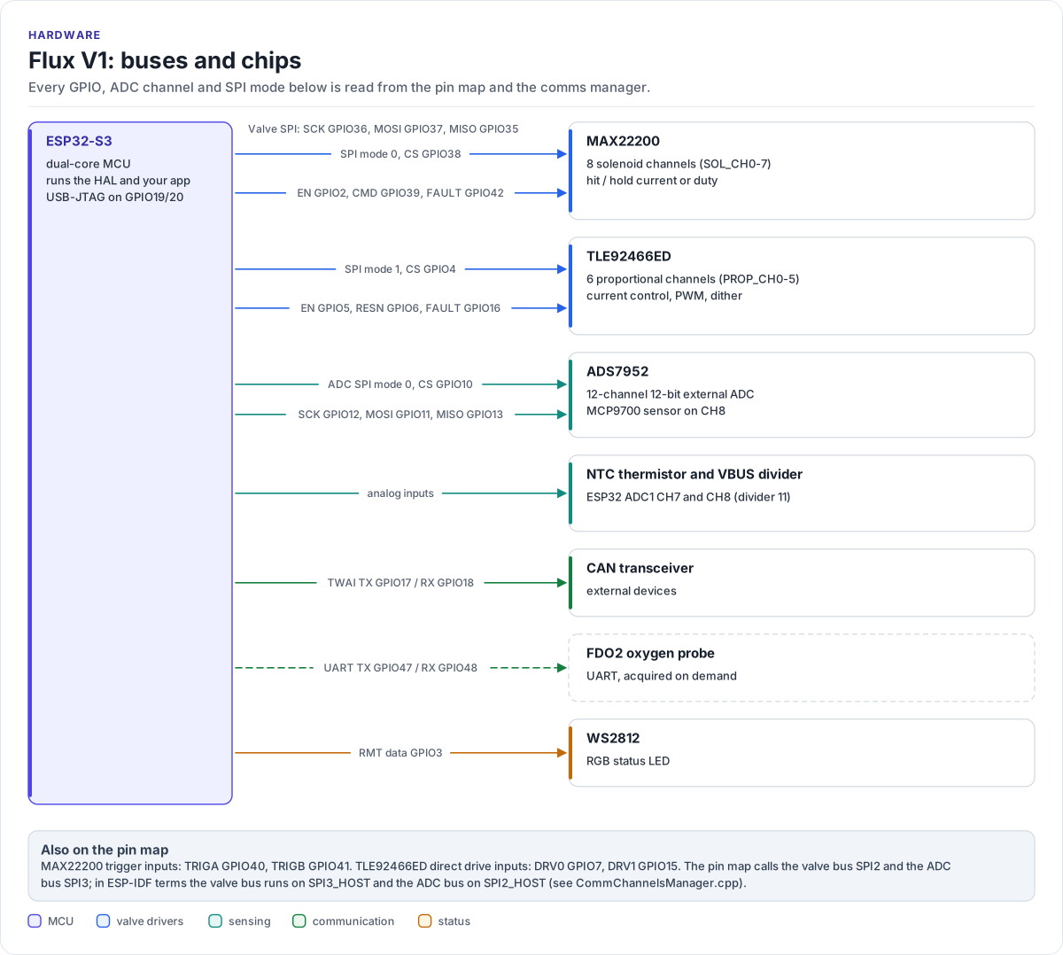
Figure description and sources
The ESP32-S3 on the left runs all the software. Each arrow to the right is one bus or signal, labelled with the GPIOs it uses. One SPI bus is shared by the two valve drivers: the MAX22200 (eight solenoid channels) and the TLE92466ED (six proportional, current-controlled channels), each with its own chip select and its own control and fault lines. A second SPI bus is dedicated to the ADS7952 12-channel external ADC. The ESP32-S3's own ADC reads the NTC thermistor and the bus-voltage divider. TWAI goes to the CAN transceiver, a UART is reserved for the FDO2 oxygen probe, and one data line drives the WS2812 status LED. The layout is drawn by hand; every GPIO number, ADC channel, chip select and SPI mode is read from the functional pin map and the comms manager, so a pin change rebuilds this figure.
Drawn from: lib/core/hf-core-drivers/internal/hf-pincfg/src/hf_functional_pin_config_flux_v1.hpp HF_FUNCTIONAL_GPIO_PIN_LIST; lib/core/hf-core-drivers/internal/hf-pincfg/src/hf_functional_pin_config_flux_v1.hpp HF_FUNCTIONAL_ADC_CHANNEL_LIST; lib/managers/CommChannelsManager.h SpiDeviceId; figure module docs/diagrams/figures/board-overview.py.
Chips and who drives them
| Chip | Job | Bus | Software |
|---|---|---|---|
| ESP32-S3 | Runs the HAL and your application (dual core) | - | ESP-IDF, lib/api/Flux.h |
| MAX22200 | Octal solenoid driver: 8 on/off valve channels with hit-and-hold control | Valve SPI, mode 0, 1 MHz | ValveManager via Max22200Handler |
| TLE92466ED | Six-channel low-side driver with current regulation, PWM and dither, for proportional valves | Valve SPI, mode 1, 1 MHz | ValveManager via Tle92466edHandler |
| ADS7952 | 12-channel, 12-bit SAR ADC (2.5 V reference) | ADC SPI, mode 0, 4 MHz | AdcManager via Ads7952Handler |
| MCP9700 | Analog temperature sensor, read on ADS7952 channel 8 | - | TemperatureManager |
| NTC thermistor | Board temperature, 10 kΩ, B = 3950, read on ESP32 ADC1 | - | TemperatureManager |
| VBUS divider | Supply-voltage monitor (divider 11) on ESP32 ADC1 | - | AdcManager |
| CAN transceiver | CAN bus at 500 kbit/s through the ESP32 TWAI controller | TWAI | CommChannelsManager |
| FDO2 probe port | UART for a PyroScience FDO2-G2 oxygen probe | UART, opened on demand | CommChannelsManager AcquireUart() |
| WS2812 | One RGB status LED | RMT | LedManager |
The SPI modes, clock rates and the CAN bit rate come from
CommChannelsManager.cpp; the NTC values from
TemperatureManager.cpp; the MAX22200 full-scale current (1000 mA,
15 kΩ RREF) from ValveManager.cpp.
SPI2 and SPI3 mean two things
The pin map names the valve bus SPI2_* and the ADC bus SPI3_*. In ESP-IDF terms the valve bus runs on
SPI3_HOST (through the GPIO matrix) and the ADC bus on SPI2_HOST (native IOMUX pins). Keep this in mind when
you read ESP-IDF logs or a logic-analyser trace.
There is no I2C bus on Flux V1: CommChannelsManager::GetI2cBus() always returns nullptr.
Pin map
Every functional pin and ADC channel, with its GPIO, polarity and pull, is on the pin map page.