Hardware
How to build the divider the driver expects, how to size it for your temperature range, and what limits the accuracy.
Part values here come from the TDK NTCG163JF103FT1S spec sheet, the driver's default part. Values marked derived are computed from that sheet's nominal resistance table for a 3.3 V, 10 kΩ / 10 kΩ divider and a 12-bit ADC; recompute them for your values.
Divider
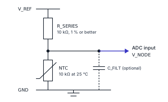
reference_voltage(V)- V_REF, the divider supply that feeds R_SERIES
series_resistance(Ω)- R_SERIES, from V_REF to the ADC node
resistance_at_25c,beta_value- The NTC, from the ADC node to GND
adc_channel- The ADC input on the node
The driver solves the divider for the thermistor:
RNTC = RSERIES · VNODE / (VREF − VNODE)
It assumes this orientation, the NTC on the low side. The voltage falls as the temperature rises.
A board with the NTC on the high side
With the thermistor from the supply to the node and the resistor to ground, the equation above returns
RSERIES² / RNTC. Return VREF − VNODE from your port's
ReadChannelV() instead of VNODE, and the driver sees the low-side divider it expects.
Supply and reference
The driver uses the node voltage in volts and reference_voltage as the divider's supply. Two consequences:
- Set
reference_voltageto the voltage that feeds R_SERIES, measured on your board, not the ADC's nominal full scale. A 1 % error in it moves the reading by about 0.5 °C at 25 °C (derived). - Supply noise goes straight into the reading. Feed the divider from the same clean rail as the ADC reference, or from a reference output if your MCU has one.
adc_resolution_bits in the configuration and GetReferenceVoltage() / GetResolutionBits() in the port are
not used in the conversion; the volts your port returns are.
Choosing the series resistor
Resolution is best where RNTC equals RSERIES. For a 10 kΩ part, 10 kΩ centres the divider on 25 °C:
| Temperature (°C) | VNODE (V) | °C per LSB |
|---|---|---|
| −35 | 3.086 | 0.08 |
| 0 | 2.415 | 0.03 |
| 25 | 1.650 | 0.03 |
| 85 | 0.418 | 0.08 |
| 125 | 0.167 | 0.22 |
Derived from the spec sheet's Table 3 for 3.3 V, 10 kΩ and a 12-bit ADC (0.81 mV per LSB); the slope is
−30.8 mV/°C at 25 °C and −3.6 mV/°C at 125 °C. For a range that
sits away from 25 °C, choose RSERIES near RNTC at its centre;
NTC::CalculateOptimalSeriesResistance(r25, beta, t_min, t_max, &r) returns the geometric mean of
RNTC at the two ends of a range, from your part's R25 and B (pass cfg.resistance_at_25c and
cfg.beta_value).
Use a 1 % or better resistor with a low temperature coefficient, and keep it away from the heat you measure.
ADC input and filtering
The ADC sees the divider's source resistance, RSERIES ∥ RNTC: 5 kΩ at 25 °C for 10 kΩ / 10 kΩ. If your ADC's sample-and-hold needs a lower source resistance, or the wire to the sensor is long, add C_FILT from the node to ground (10 nF to 100 nF is common). The node then settles with a time constant of source resistance × C_FILT, 0.5 ms for 5 kΩ and 100 nF: wait several time constants after powering the divider before sampling.
Averaging in the driver (sample_count) reduces random ADC noise; it does not remove an offset or a gain
error. Use your MCU's ADC calibration for those (on ESP32, the adc_cali driver).
Self-heating
The current through the divider heats the thermistor. The power in the NTC is largest when RNTC = RSERIES: VREF² / (4 · RSERIES), 272 µW for 3.3 V and 10 kΩ (derived). The temperature rise is that power divided by the dissipation constant of the mounted part, which depends on the board; the TDK spec sheet in this repository does not state one. With 1 mW/°C it would be 0.27 °C.
To reduce it: use a larger R25 and RSERIES (100 kΩ parts dissipate a tenth as much), or power the divider from a GPIO only while you sample.
Part limits
| Parameter | NTCG163JF103FT1S |
|---|---|
| R25 | 10 kΩ ± 1 % |
| B25/85 | 3435 K ± 1 % |
| Operating temperature | −40 °C to +150 °C |
| Maximum rated power | 100 mW at 25 °C, still air |
| Size | 1.6 mm × 0.8 mm × 0.8 mm (0603) |
A 1 % R25 tolerance alone is about ±0.26 °C at 25 °C (derived: 1 % ÷ (B / T²)). The spec sheet's Table 3 gives the minimum, nominal and maximum resistance from −40 °C to +150 °C in 5 °C steps; the driver's host tests check its conversions against the nominal column.
The driver's default window is −40 °C to +125 °C (min_temperature, max_temperature). Widen it to use the
part up to +150 °C.
Supported part types
NtcType |
Part |
|---|---|
NtcG163Jf103Ft1S |
TDK NTCG163JF103FT1S, spec sheet in docs/datasheet/ |
NtcG163Jft103Ft1S |
Not found in TDK's listings; same values |
NtcG164Jf103Ft1S |
Not in TDK's listings; same values |
Custom |
Any NTC: set R25 and B (Configuration) |
All three TDK types load R25 = 10 kΩ and B = 3435 K. For any other thermistor, use Custom with the values from its
datasheet.
Reference documents
| Document | What it is for |
|---|---|
| NTCG163JF103FT1S spec sheet | R25, B, power, resistance table from −40 °C to +150 °C |
| TDK NTC chip thermistors | The NTCG family and other values |
| ESP-IDF ADC oneshot driver | Reading and calibrating the ADC on ESP32 |
Next
Conversion methods shows how far the Beta equation is from the table across the range; Porting writes the ADC port.