Porting
Run the driver on a new MCU by writing one class: the SPI interface.
The driver never calls your SDK directly. It calls eight methods on a class you derive from
max22200::SpiInterface<Self> (in inc/max22200_spi_interface.hpp). The base
class uses CRTP: the calls are resolved at compile time, so there are no virtual functions, no vtable and nothing
to allocate.
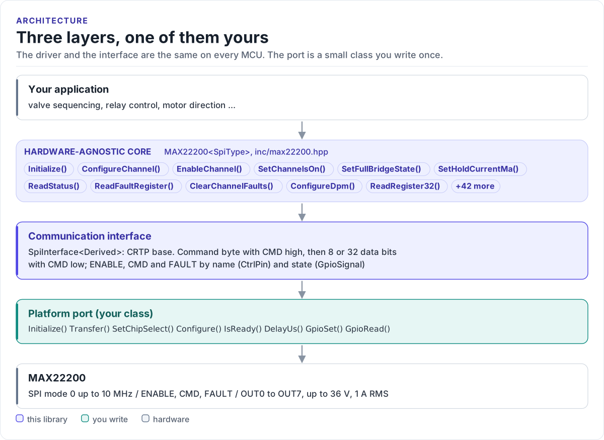
Figure description and sources
From top to bottom. Your application talks to one MAX22200
Drawn from: inc/max22200.hpp MAX22200 public calls; inc/max22200_spi_interface.hpp SpiInterface; figure module docs/diagrams/figures/driver-layers.py.
What you implement
| Method | Contract |
|---|---|
Initialize() |
Bring the SPI peripheral and the GPIOs up. Called first by the driver's Initialize() |
Configure(hz, mode, msb_first) |
Called with 10 MHz, mode 0, true. Apply it, or keep a lower clock |
Transfer(tx, rx, len) |
One blocking full-duplex transaction of len bytes (1 or 4), CS low for all of it |
GpioSet(pin, signal) |
Drive ENABLE or CMD: ACTIVE is high for both |
GpioRead(pin, signal) |
Read FAULT: low is ACTIVE. Return false if the pin is not wired |
DelayUs(us) |
Block for at least that long (the 0.5 ms enable time) |
SetChipSelect(state) |
Required by the base class; the driver does not call it |
IsReady() |
Required by the base class; the driver does not call it |
The port
class MySpi : public max22200::SpiInterface<MySpi> {
public:
  // Board wiring: ENABLE and CMD are MCU outputs, FAULT is an input with a pull-up.
  static constexpr int kEnablePin = 4;
  static constexpr int kCmdPin = 5;
  static constexpr int kFaultPin = 6;

  // Cap the clock: 1 MHz for bring-up, at most 10 MHz alone or 5 MHz in a daisy chain.
  explicit MySpi(uint32_t max_clock_hz = 10000000) : max_clock_hz_(max_clock_hz) {}

  bool Initialize() { return true; }

  // The driver calls this once from Initialize(): 10 MHz, mode 0, MSB first.
  bool Configure(uint32_t speed_hz, uint8_t mode, bool msb_first) {
    const uint32_t hz = speed_hz < max_clock_hz_ ? speed_hz : max_clock_hz_;
    return mode == 0 && msb_first && platform_spi_init(hz, mode);
  }

  bool IsReady() const { return true; }

  // One blocking, full-duplex transaction: CS low, `length` bytes, CS high, then return.
  bool Transfer(const uint8_t* tx, uint8_t* rx, std::size_t length) {
    return platform_spi_transfer(tx, rx, length);
  }

  void SetChipSelect(bool) {}   // Transfer() owns CS; the driver never calls this

  void DelayUs(uint32_t us) { platform_delay_us(us); }

  // ENABLE and CMD are active high, FAULT is active low (open drain).
  void GpioSet(max22200::CtrlPin pin, max22200::GpioSignal signal) {
    const bool high = signal == max22200::GpioSignal::ACTIVE;
    if (pin == max22200::CtrlPin::ENABLE) platform_gpio_write(kEnablePin, high);
    if (pin == max22200::CtrlPin::CMD) platform_gpio_write(kCmdPin, high);
  }

  bool GpioRead(max22200::CtrlPin pin, max22200::GpioSignal& signal) {
    if (pin != max22200::CtrlPin::FAULT) return false;
    signal = platform_gpio_read(kFaultPin) ? max22200::GpioSignal::INACTIVE
                                           : max22200::GpioSignal::ACTIVE;
    return true;
  }

private:
  uint32_t max_clock_hz_;
};
Rules the transfer must follow:
- SPI mode 0, MSB first, at most 10 MHz (5 MHz with daisy-chained parts on the bus).
- One transaction per call. CS goes low before the first byte and high after the last; never split a call, never merge two. The chip counts clocks and flags a communication error on a wrong count.
- Return after CS is high. The driver raises CMD, calls
Transfer()for the command byte and lowers CMD as soon as it returns. CMD must still be high at the CS rising edge, so a queued or DMA transfer that returns early breaks every access. - Fill
rx. The driver reads the fault byte and register values from it. - Return
falseonly for a bus failure. The driver turns it intoCOMMUNICATION_ERROR.
Pin levels
| Pin (MCU side) | ACTIVE level |
At power-up |
|---|---|---|
ENABLE (output) |
high | low: chip asleep |
CMD (output) |
high | low |
FAULT (input, pull-up) |
low | low until the first STATUS read (UVM) |
A board with an inverting buffer flips the level in your GpioSet() or GpioRead(); the driver only deals in
ACTIVE and INACTIVE. If ENABLE is tied high on your board, ignore it in GpioSet(); if FAULT is not wired,
return false from GpioRead() and poll ReadStatus() instead.
Reference implementation
The ESP32 examples use esp32_max22200_bus.hpp: an ESP-IDF
spi_master port with spi_device_transmit() (blocking, CS handled by the peripheral), esp_rom_delay_us() and
GPIOs for ENABLE, CMD, FAULT, TRIGA and TRIGB (TRIGA and TRIGB start low, inactive). Start from it for any ESP-IDF
target.
Check your port
- Build it: the port on this page is compiled by the host CI from
tests/docs/, with the driver instantiated over it. - Call
Initialize().OKproves the command and data phases work: the driver reads STATUS, writes it and reads it back. - Write a channel with
ConfigureChannel(), read it withReadRegister32()and compare the raw values (SPI protocol decodes them). - Watch
GetStatistics():failed_transfersshould stay at zero.
Threads
The driver is not thread-safe. Give each MAX22200 one owner task, or guard every call on a driver object (and its
port) with one mutex. Other devices can share the SPI bus: the MAX22200 only sees transfers with its own CS, and
its command stays in force between them, so locking the bus inside each Transfer() call is enough.