Porting
Run the driver on a new MCU by writing one class: the communication interface for SPI or UART.
The driver never calls your SDK directly. It calls a few methods on a class you derive from
tmc51x0::SpiCommInterface<Self> or tmc51x0::UartCommInterface<Self> (in
inc/tmc51x0_comm_interface.hpp). The base classes use CRTP: the calls are
resolved at compile time, so there are no virtual functions and no vtable.
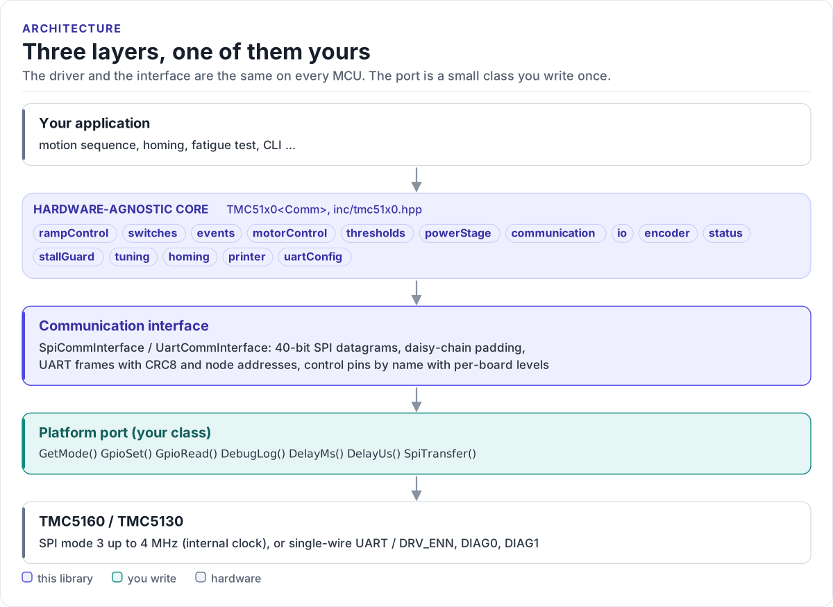
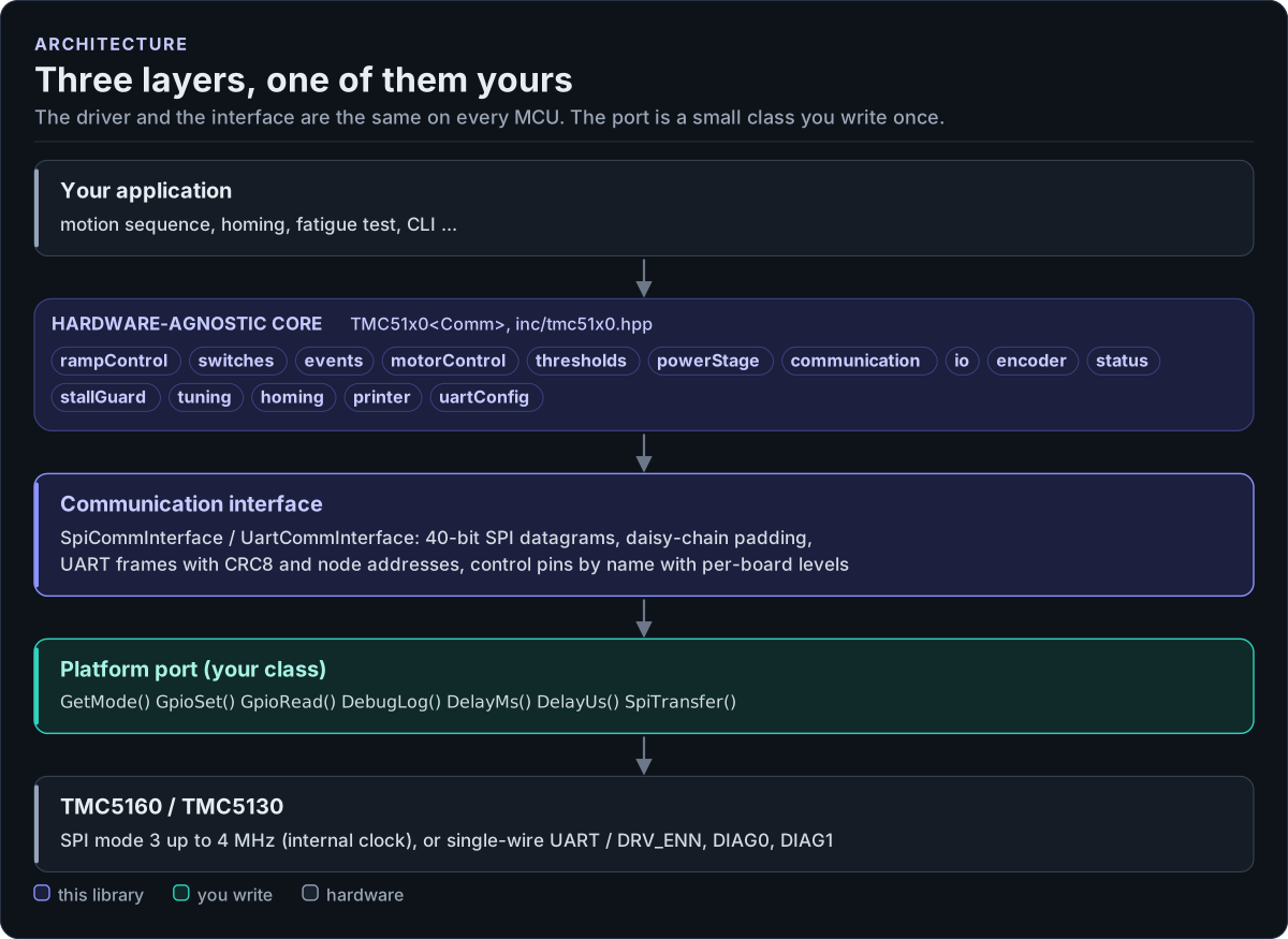
Figure description and sources
From top to bottom. Your application talks to one TMC51x0
Drawn from: inc/tmc51x0.hpp TMC51x0 members; inc/tmc51x0_comm_interface.hpp SpiCommInterface; figure module docs/diagrams/figures/driver-layers.py.
What you implement
| Method | SPI | UART | Contract |
|---|---|---|---|
GetMode() |
yes | yes | Return CommMode::SPI or CommMode::UART |
SpiTransfer(tx, rx, length) |
yes | One full-duplex transfer of length bytes with CSN low throughout. length is a multiple of 5 |
|
UartSend(data, length) |
yes | Send one frame (8 bytes for a write, 4 for a read request) and remove the echo | |
UartReceive(data, length) |
yes | Return success only when all length bytes (an 8-byte reply) arrived |
|
SetNaiPin(active), GetNaoPin() |
yes | Drive NAI / read NAO for sequential addressing; return UNSUPPORTED when not wired |
|
GpioSet(pin, signal) |
yes | yes | Drive a control pin (at least EN, DRV_ENN) to ACTIVE / INACTIVE |
GpioRead(pin) |
yes | yes | Read a pin as ACTIVE / INACTIVE; return UNSUPPORTED / INVALID_VALUE for pins you do not have |
DelayMs(ms), DelayUs(us) |
yes | yes | Block for at least that long |
DebugLog(level, tag, format, va_list) |
yes | yes | Print one line (0 = error ... 4 = verbose), or do nothing |
SetClkFreq(hz) |
optional | optional | Drive the CLK pin: 0 = tie low for the internal clock. Default: UNSUPPORTED |
SetPowerEnabled(on) |
optional | optional | Switch the chip's supply, for HardReset() by power cycle. Default: UNSUPPORTED |
All methods are noexcept and return tmc51x0::Result<...> where the table shows a result.
SPI port
class MySpi : public tmc51x0::SpiCommInterface<MySpi> {
public:
  tmc51x0::CommMode GetMode() const noexcept { return tmc51x0::CommMode::SPI; }

  // One full-duplex transfer of `length` bytes (5 per chip in the chain), SPI mode 3, CSN low throughout.
  tmc51x0::Result<void> SpiTransfer(const uint8_t* tx, uint8_t* rx, size_t length) noexcept {
    if (!platform_spi_transfer(tx, rx, length)) {
      return tmc51x0::Result<void>(tmc51x0::ErrorCode::COMM_ERROR);
    }
    return tmc51x0::Result<void>();
  }

  // ACTIVE / INACTIVE to a GPIO level. DRV_ENN is active low: ACTIVE (enabled) drives it low.
  tmc51x0::Result<void> GpioSet(tmc51x0::TMC51x0CtrlPin pin, tmc51x0::GpioSignal signal) noexcept {
    const int gpio = GpioOf(pin);
    const bool level = (signal == tmc51x0::GpioSignal::ACTIVE) == levels_.GetActiveLevel(pin);
    if (gpio < 0 || !platform_gpio_write(gpio, level)) {
      return tmc51x0::Result<void>(tmc51x0::ErrorCode::INVALID_VALUE);
    }
    return tmc51x0::Result<void>();
  }

  tmc51x0::Result<tmc51x0::GpioSignal> GpioRead(tmc51x0::TMC51x0CtrlPin pin) noexcept {
    bool level = false;
    const int gpio = GpioOf(pin);
    if (gpio < 0 || !platform_gpio_read(gpio, level)) {
      return tmc51x0::Result<tmc51x0::GpioSignal>(tmc51x0::ErrorCode::INVALID_VALUE);
    }
    return tmc51x0::Result<tmc51x0::GpioSignal>(level == levels_.GetActiveLevel(pin)
                                                    ? tmc51x0::GpioSignal::ACTIVE
                                                    : tmc51x0::GpioSignal::INACTIVE);
  }

  void DelayMs(uint32_t ms) noexcept { platform_delay_us(ms * 1000U); }
  void DelayUs(uint32_t us) noexcept { platform_delay_us(us); }

  // Route driver logs to your logger (level 0 = error ... 4 = verbose), or leave it empty.
  void DebugLog(int /*level*/, const char* /*tag*/, const char* /*format*/, va_list /*args*/) noexcept {}

private:
  static int GpioOf(tmc51x0::TMC51x0CtrlPin pin) noexcept {
    switch (pin) {
    case tmc51x0::TMC51x0CtrlPin::EN: return 6;      // DRV_ENN
    case tmc51x0::TMC51x0CtrlPin::DIAG0: return 7;   // optional: interrupt / stall output
    case tmc51x0::TMC51x0CtrlPin::DIAG1: return 8;   // optional: position compare output
    default: return -1;                              // not wired on this board
    }
  }

  tmc51x0::PinActiveLevels levels_{};  // defaults: DRV_ENN active low, the other pins active high
};
Rules the transfer must follow:
- SPI mode 3, MSB first, up to 4 MHz on the chip's internal clock (8 MHz with a 16 MHz external clock).
- One transaction per call. CSN goes low before the first byte and high after the last. In a daisy chain the buffer covers every chip; never split it.
- Full duplex, same length. Fill
rxwith exactlylengthbytes. - Return an error only for a bus failure. Status bits and register contents are the driver's job.
- Serialise access. The interface uses per-object scratch buffers: one transfer at a time per port object.
UART port
class MyUart : public tmc51x0::UartCommInterface<MyUart> {
public:
  tmc51x0::CommMode GetMode() const noexcept { return tmc51x0::CommMode::UART; }

  // Send one datagram (8 bytes for a write, 4 for a read request). On a single-wire bus the
  // transmitted bytes echo back: discard them here, or read them away in UartReceive().
  tmc51x0::Result<void> UartSend(const uint8_t* data, size_t length) noexcept {
    return platform_uart_write(data, length) ? tmc51x0::Result<void>()
                                             : tmc51x0::Result<void>(tmc51x0::ErrorCode::COMM_ERROR);
  }

  // Block until exactly `length` bytes (an 8-byte reply) arrived, or fail.
  tmc51x0::Result<void> UartReceive(uint8_t* data, size_t length) noexcept {
    return platform_uart_read(data, length, 10) ? tmc51x0::Result<void>()
                                                : tmc51x0::Result<void>(tmc51x0::ErrorCode::TIMEOUT);
  }

  // NAI (SDI_CFG1) selects which chip answers at address 0 while addresses are programmed.
  tmc51x0::Result<void> SetNaiPin(bool active) noexcept {
    return platform_gpio_write(kNaiGpio, active) ? tmc51x0::Result<void>()
                                                 : tmc51x0::Result<void>(tmc51x0::ErrorCode::COMM_ERROR);
  }

  tmc51x0::Result<bool> GetNaoPin() noexcept {
    return tmc51x0::Result<bool>(tmc51x0::ErrorCode::UNSUPPORTED);  // NAO not wired back on this board
  }

  tmc51x0::Result<void> GpioSet(tmc51x0::TMC51x0CtrlPin pin, tmc51x0::GpioSignal signal) noexcept {
    if (pin != tmc51x0::TMC51x0CtrlPin::EN) {
      return tmc51x0::Result<void>(tmc51x0::ErrorCode::UNSUPPORTED);
    }
    const bool enabled = signal == tmc51x0::GpioSignal::ACTIVE;
    return platform_gpio_write(kDrvEnnGpio, !enabled) ? tmc51x0::Result<void>()  // DRV_ENN: low = enabled
                                                      : tmc51x0::Result<void>(tmc51x0::ErrorCode::COMM_ERROR);
  }

  tmc51x0::Result<tmc51x0::GpioSignal> GpioRead(tmc51x0::TMC51x0CtrlPin /*pin*/) noexcept {
    return tmc51x0::Result<tmc51x0::GpioSignal>(tmc51x0::ErrorCode::UNSUPPORTED);
  }

  void DelayMs(uint32_t ms) noexcept { platform_delay_us(ms * 1000U); }
  void DelayUs(uint32_t us) noexcept { platform_delay_us(us); }
  void DebugLog(int /*level*/, const char* /*tag*/, const char* /*format*/, va_list /*args*/) noexcept {}

private:
  static constexpr int kNaiGpio = 9;
  static constexpr int kDrvEnnGpio = 6;
};
On a single wire the MCU's TX and RX are joined, so every frame you send comes back on RX. The driver expects
UartReceive() to return the chip's reply only: flush the receive buffer after sending (as the ESP32 port does),
or read and discard length echo bytes. Choose a baud rate between 9000 and fCLK/16; the chip detects
it from each frame's sync nibble. Allow for the reply delay (SENDDELAY, 8 bit times by default) in the receive
timeout.
Control pins
GpioSet() and GpioRead() receive a pin name (TMC51x0CtrlPin) and a state (GpioSignal). Your port turns a
state into a level. tmc51x0::PinActiveLevels holds the datasheet levels; GetActiveLevel(pin) returns the level
of the active state:
| Pin | Datasheet active level | Meaning of ACTIVE |
|---|---|---|
EN (DRV_ENN) |
low | Power stage enabled |
REFL_STEP, REFR_DIR as switches |
low (configurable in SW_MODE) |
Switch pressed |
STEP, DIR, DCEN, DCIN |
high | |
DIAG0, DIAG1 |
high (push-pull default) | Event signalled |
SPI_MODE, SD_MODE |
high | SPI interface, external STEP/DIR |
The driver drives EN in Enable() / Disable(), and SPI_MODE / SD_MODE only in
io.SetOperatingMode() / GetOperatingMode(), for boards that wire the straps to GPIOs. The other pins exist
for applications that want them; a port may return UNSUPPORTED for pins it does not wire. Change a level with
PinActiveLevels::SetActiveLevel() when your board inverts a signal.
Reference implementation
The ESP32 examples use esp32_tmc51x0_bus.hpp:
Esp32SPI on the ESP-IDF spi_master driver with an optional mutex, and Esp32UART on the UART driver, with
FreeRTOS delays, ESP_LOG output, pin mapping through TMC51x0PinConfig and CLK control. Start from it for any
ESP-IDF target.
Check your port
- Build it: both ports on this page are compiled by the host CI from
tests/docs/, with the driver instantiated over them. - Read
IOIN(io.ReadIcVersion()):0x30for a TMC5160,0x11for a TMC5130.0x00or0xFFmeans the bus does not work. - Run
Initialize()andstatus.VerifySetup(): it reads back the configuration and logs mismatches. - Call
motorControl.Enable()and checkio.ReadInputStatus().Value().drv_ennisfalse(pin low).
Threads
The driver is not thread-safe. Give each chip one owner task, or guard every call on a driver object (and its port) with one mutex. Chips on a shared bus share the port, so they share the mutex.
Next: Examples.