Porting
Run the driver on a new MCU by writing one class: the I2C interface.
The driver never calls your SDK directly. It calls three methods on a class you derive from
pca9685::I2cInterface<Self> (in inc/pca9685_i2c_interface.hpp). The
base class uses CRTP: the calls are resolved at compile time, so there are no virtual functions, no vtable and
nothing to allocate.
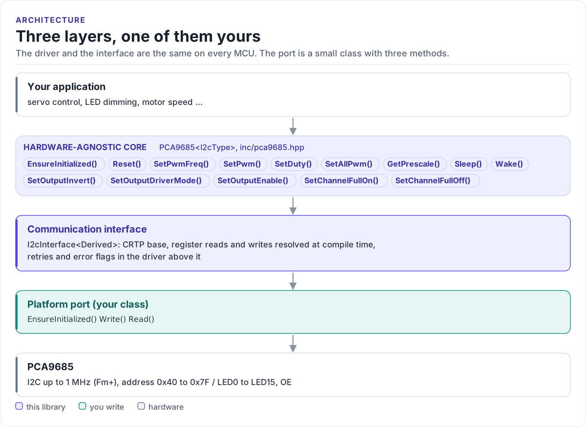
Figure description and sources
From top to bottom. Your application talks to one PCA9685
Drawn from: inc/pca9685.hpp PCA9685 public calls; inc/pca9685_i2c_interface.hpp I2cInterface; figure module docs/diagrams/figures/driver-layers.py.
What you implement
| Method | Contract |
|---|---|
EnsureInitialized() |
Bring the bus up on the first call; return true at once afterwards. false stops the driver from starting |
Write(addr, reg, data, len) |
One transaction: START, addr + W, reg, len bytes, STOP. true only if every byte was acknowledged |
Read(addr, reg, data, len) |
One transaction: START, addr + W, reg, repeated START, addr + R, len bytes, STOP |
DelayUs(us) |
Optional, recommended: wait at least us microseconds. The driver calls it with 500 after it clears MODE1.SLEEP, for the oscillator start-up time (datasheet Table 5, note 2) |
GpioSet(pin, signal) |
Optional: drive the OE pin; called by SetOutputEnable() (see below) |
addr is the 7-bit address; shift it left yourself if your SDK wants the 8-bit form. The driver writes at most
four data bytes per call and reads one.
The optional methods are found at compile time: a port without them still builds. Without DelayUs() the driver
covers the 500 µs start-up with 13 one-byte reads of MODE1, enough at any bus clock up to 1 MHz, so give your port
a DelayUs() if its Read() can return without running a bus transaction.
I2C port
class MyI2c : public pca9685::I2cInterface<MyI2c> {
public:
// Bring the bus up once; later calls return true at once.
bool EnsureInitialized() noexcept {
if (!ready_) {
ready_ = platform_i2c_init();
}
return ready_;
}
// One write transaction: START, address + W, register, data bytes, STOP.
bool Write(uint8_t addr, uint8_t reg, const uint8_t* data, size_t len) noexcept {
uint8_t frame[1 + 4]; // the driver writes at most 4 data bytes
if (len > sizeof(frame) - 1) {
return false;
}
frame[0] = reg;
for (size_t i = 0; i < len; ++i) {
frame[1 + i] = data[i];
}
return platform_i2c_write(addr, frame, len + 1);
}
// Register read: START, address + W, register, repeated START, address + R, data, STOP.
bool Read(uint8_t addr, uint8_t reg, uint8_t* data, size_t len) noexcept {
return platform_i2c_write_read(addr, ®, 1, data, len);
}
// Optional: wait at least `us` microseconds. The driver uses it for the 500 us oscillator start-up.
void DelayUs(uint32_t us) noexcept { platform_delay_us(us); }
private:
bool ready_ = false;
};
Rules the transfer must follow:
- One call, one transaction. Never split a channel's four bytes into separate transactions: the chip updates the outputs at the STOP, and the register pointer does not carry over.
- Repeated START for reads. Write the register byte, then read without a STOP in between (Figure 22 of the datasheet).
- Return
falsefor a NACK or a bus error. The driver retries and sets the error flags; do not retry in the port as well. - Bounded time-outs. A stuck bus should fail the call, not block forever. The chip resets its own interface when SCL or SDA stays low for 25 ms.
- Clock up to 1 MHz. Start at 100 kHz for bring-up; 400 kHz suits most boards.
The OE pin
OE is active low (datasheet section 7.4): low, the outputs follow their registers; high, they take the
MODE2.OUTNE state, low by default. If OE is wired to a GPIO, declare GpioSet() in your port and map
GpioSignal::ACTIVE (outputs enabled) to a low level:
// OE is active low: ACTIVE (outputs enabled) is a LOW level, INACTIVE (blanked) a HIGH level.
void GpioSet(pca9685::CtrlPin pin, pca9685::GpioSignal signal) noexcept {
  if (pin == pca9685::CtrlPin::OE) {
    platform_gpio_write(OE_GPIO, signal == pca9685::GpioSignal::INACTIVE);
  }
}
SetOutputEnable(true) calls GpioSet(CtrlPin::OE, GpioSignal::ACTIVE) and SetOutputEnable(false) calls it
with INACTIVE; the base class helpers GpioSetActive() and GpioSetInactive() reach your GpioSet() too. A
port without GpioSet() inherits a do-nothing default, for boards with OE tied low. The driver never drives OE
on its own, so your port can hold the outputs blanked from power-up until the channels are programmed.
Reference implementation
The ESP32 examples use esp32_pca9685_bus.hpp: an ESP-IDF
i2c_master port that caches the device handle, with a RetryDelay() (vTaskDelay of 1 ms) that you pass to
SetRetryDelay(). Start from it for any ESP-IDF target.
Check your port
- Build it: the port on this page is compiled by the host CI from
tests/docs/, with the driver instantiated over it. - Call
EnsureInitialized():trueproves a write to MODE1 was acknowledged at your address. - Call
SetPwmFreq(50.0f), thenGetPrescale(): 121 proves reads and writes both work. - Put a scope or logic analyser on LED0 after
SetDuty(0, 0.5f): a 50 % square wave at about 50 Hz.
Threads
The driver is not thread-safe. Give each PCA9685 one owner task, or guard every call on a driver object with one mutex. Several chips on one bus share the port, so guard the port too.