Architecture
How the driver is put together: three layers, what each owns, and how one call reaches the chip.
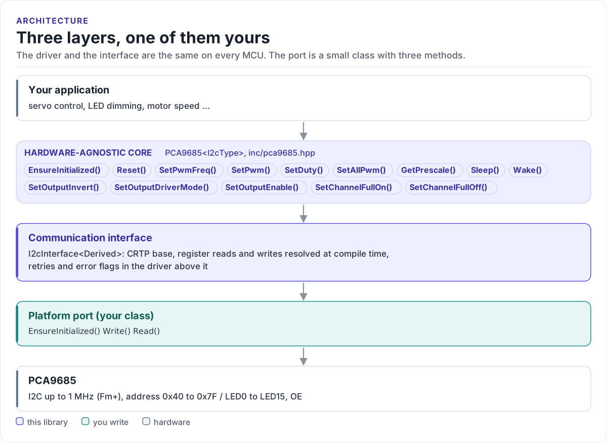
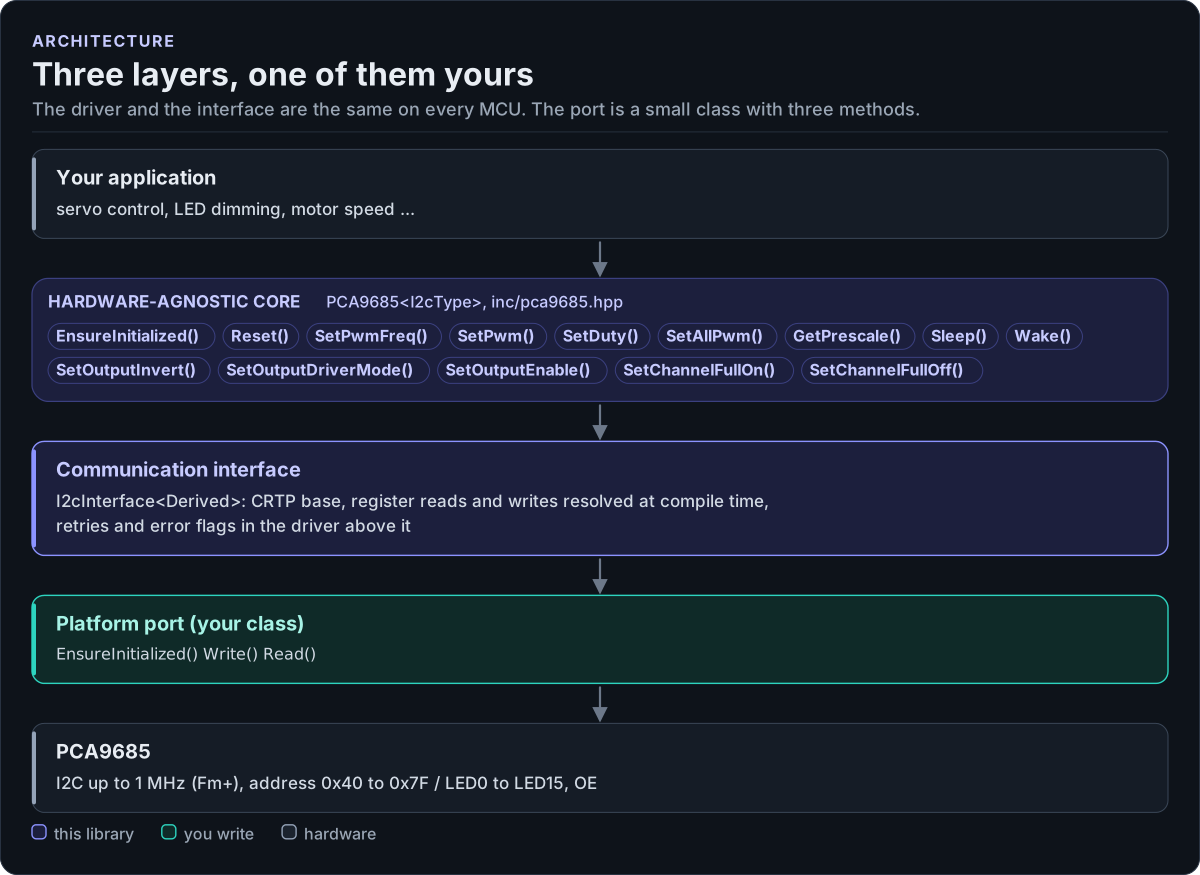
Figure description and sources
From top to bottom. Your application talks to one PCA9685
Drawn from: inc/pca9685.hpp PCA9685 public calls; inc/pca9685_i2c_interface.hpp I2cInterface; figure module docs/diagrams/figures/driver-layers.py.
The three layers
| Layer | Where | You change it when |
|---|---|---|
Hardware-agnostic core: PCA9685<I2cType> |
inc/pca9685.hpp, src/pca9685.ipp |
Never, for a new board |
Communication interface: I2cInterface<Derived> |
inc/pca9685_i2c_interface.hpp |
Never |
| Platform port: your class, three methods | Your project | Once per MCU or board (Porting) |
Everything above the port is the same on ESP32, STM32, a Linux host or the unit-test model. That is how the host tests run the real driver code without hardware.
How one call reaches the chip
sequenceDiagram
    participant A as Application
    participant D as PCA9685 core
    participant P as Your port
    participant C as PCA9685 chip
    A->>D: SetDuty(0, 0.075f)
    D->>D: clamp to 0..1, OFF = lround(0.075 x 4095) = 307
    D->>D: EnsureInitialized() (first call only: Reset)
    D->>P: Write(0x40, LED0_ON_L, {00 00 33 01}, 4)
    P->>C: START, 0x40 + W, 0x06, 4 bytes, STOP
    C-->>P: ACK
    P-->>D: true (on NACK: false, retried up to SetRetries() times)
    D-->>A: true / false + Error flag
Why CRTP
The interface is a class template parameter, not a virtual base class. The compiler sees your port's methods
directly and inlines them; the driver has no vtable, allocates nothing and needs no RTTI. The cost is that the
driver type names the port: PCA9685<MyI2c>. Code that has to work with several port types takes the driver as
a template parameter too.
Lazy initialisation
The constructor only stores the bus pointer and the address; it never touches the bus. The first call that needs
the chip runs EnsureInitialized(), which calls the port's EnsureInitialized() and then Reset() (MODE1 =
0x00). After that, IsInitialized() is true and no call repeats it. Call EnsureInitialized() yourself at
start-up to find wiring problems early, at a point where you can report them.
Errors without exceptions
Each call returns bool. On false, the reason is in two places:
GetErrorFlags(): a bitmask ofErrorvalues that accumulates until you clear it withClearErrorFlags()orClearError().GetLastError(): the most recent error; a later successful call sets it back toError::None.
Register accesses retry: one attempt plus SetRetries() more (3 by default), with an optional callback between
attempts (SetRetryDelay()).
Source map
| Path | Contents |
|---|---|
inc/pca9685.hpp |
PCA9685<I2cType>: registers, error flags, the public API |
src/pca9685.ipp |
Template implementation, included by the header |
inc/pca9685_i2c_interface.hpp |
I2cInterface<Derived>, CtrlPin, GpioSignal |
inc/pca9685_version.h.in |
Version header template, filled in by CMake |
tests/ |
Host unit tests and the compiled documentation snippets |
examples/esp32/ |
ESP-IDF applications and the ESP-IDF port |