Porting
Run the driver on a new MCU by writing one class: the SPI interface.
The driver never calls your SDK directly. It calls eight methods on a class you derive from
isf15acp4::SpiInterface<Self> (in inc/isf15acp4_spi_interface.hpp). The
base class uses CRTP: the calls are resolved at compile time, so there are no virtual functions, no vtable and
nothing to allocate.
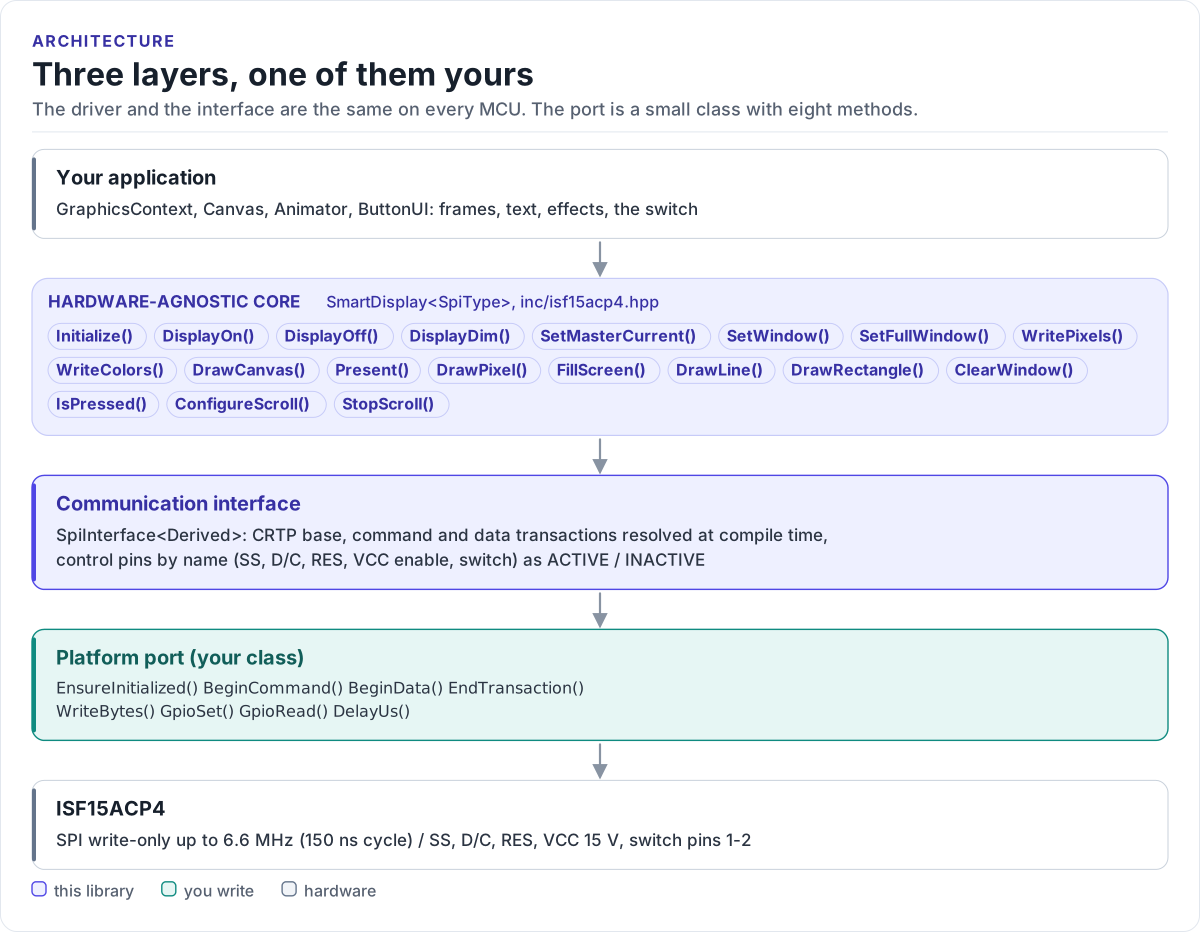
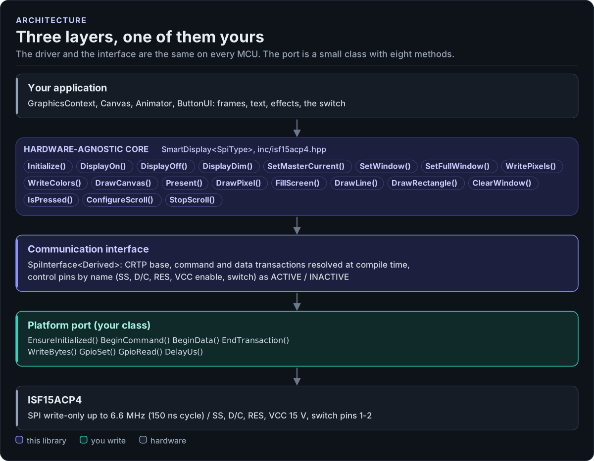
Figure description and sources
From top to bottom. Your application draws into a GraphicsContext and calls one SmartDisplay
Drawn from: inc/isf15acp4.hpp SmartDisplay public calls; inc/isf15acp4_spi_interface.hpp SpiInterface; figure module docs/diagrams/figures/driver-layers.py.
What you implement
| Method | Contract |
|---|---|
EnsureInitialized() |
Bring SPI and GPIOs up; true when ready, also on later calls |
BeginCommand() |
D/C low, then SS low: a command and its parameters follow |
BeginData() |
D/C high, then SS low: display data follows |
EndTransaction() |
SS high, after the last bit has left |
WriteBytes(data, len) |
Send len bytes (up to 12,288), blocking until sent |
GpioSet(pin, signal) |
Drive SS, D/C, RES or VCC enable Active / Inactive |
GpioRead(pin) |
true when Switch is pressed, else false |
DelayUs(us) |
Wait at least that long (the driver uses 3, 10 and 1000) |
All return bool except EndTransaction(), GpioSet() and DelayUs(), which return void.
SPI port
class MySpi : public isf15acp4::SpiInterface<MySpi> {
public:
  // Your board's GPIO numbers.
  static constexpr int kCs = 10, kDc = 13, kRes = 14, kVccEn = 9, kSwitch = 8;

  bool EnsureInitialized() noexcept {
    platform_gpio_write(kCs, true);       // SS idle high
    platform_gpio_write(kVccEn, false);   // 15 V drive supply off until after reset
    return platform_spi_init();
  }

  // D/C low = command, high = data; SS low for the whole transaction.
  bool BeginCommand() noexcept { return begin(false); }
  bool BeginData() noexcept { return begin(true); }
  void EndTransaction() noexcept { platform_gpio_write(kCs, true); }

  // Must not return before the last bit is on the wire: SS rises right after.
  bool WriteBytes(const uint8_t* data, std::size_t len) noexcept {
    return platform_spi_write(data, len);
  }

  void GpioSet(isf15acp4::CtrlPin pin, isf15acp4::GpioSignal signal) noexcept {
    const bool active = signal == isf15acp4::GpioSignal::Active;
    switch (pin) {
      case isf15acp4::CtrlPin::ChipSelect:  platform_gpio_write(kCs, !active); break;   // SS active low
      case isf15acp4::CtrlPin::DataCommand: platform_gpio_write(kDc, active); break;    // high = data
      case isf15acp4::CtrlPin::Reset:       platform_gpio_write(kRes, !active); break;  // RES# active low
      case isf15acp4::CtrlPin::VccEnable:   platform_gpio_write(kVccEn, active); break;
      case isf15acp4::CtrlPin::Switch:      break;                                      // input only
    }
  }

  // The switch closes pins 1-2; wired to GND with a pull-up, pressed reads low.
  bool GpioRead(isf15acp4::CtrlPin pin) noexcept {
    return pin == isf15acp4::CtrlPin::Switch && !platform_gpio_read(kSwitch);
  }

  void DelayUs(uint32_t us) noexcept { platform_delay_us(us); }

private:
  bool begin(bool data) noexcept {
    platform_gpio_write(kDc, data);
    platform_gpio_write(kCs, false);
    return true;
  }
};
Rules the transfer must follow:
- SPI mode 0 (mode 3 also meets the datasheet), MSB first, at most 6.6 MHz.
- One SS-low transaction per Begin / End pair. The driver calls
WriteBytes()one or more times inside it (a command's opcode, then its parameters; a frame in chunks of up to 128 bytes); keep SS low across all of them. - Blocking writes.
WriteBytes()must not return while bytes are still queued:EndTransaction()raises SS right after it, and the display drops a byte cut short. With DMA, wait for completion. - No MISO. The display has no data output; leave MISO unconnected or free for other devices.
- Return
falseonly for a bus failure. The driver turns it intoError::SpiWrite.
Control pins
The driver addresses pins by name and abstract level. Your port decides the physical level:
| Pin | Driver use | Active is |
|---|---|---|
ChipSelect |
Inactive at start |
Low |
DataCommand |
Active at start |
High (data) |
Reset |
Active 3 µs, then Inactive |
Low (RES# held in reset) |
VccEnable |
Active after reset |
Supply on |
Switch |
Read by IsPressed() |
Pressed |
Reset follows the other pins: Active is the asserted level, which for RES# is low. Initialize() drives it
Active for at least 3 µs, then Inactive (high), and waits 10 µs before the first command (SSD1331 power-on
sequence, reset completion 2 µs maximum).
Reference implementation
The ESP32 examples use esp32_isf15acp4_spi_adapter.hpp:
an ESP-IDF spi_master device in mode 0 with SS as a GPIO, spi_device_polling_transmit() for blocking writes,
an input with pull-up for the switch and esp_rom_delay_us() / vTaskDelay() for delays. Start from it for any
ESP-IDF target.
Check your port
- Build it: the port on this page is compiled by the host CI from
tests/docs/, with the driver instantiated over it. - With a logic analyser on SS, D/C and SCK, call
Initialize(): you should see 21 command transactions (the init table) and two window commands, each with SS low around its bytes, and RES high at the end. - Call
FillScreen(isf15acp4::colors::White), thenFillScreen(isf15acp4::colors::Black): the whole panel turns white, then dark. (White and black do not depend on byte order; for colours see Troubleshooting.) - Read
IsPressed()with the button held and released.
Threads
The driver is not thread-safe. Give each display one owner task, or guard every call on a driver object (and its
port) with one mutex. Several displays on one SPI bus need a separate SS per display, and the bus must not be used
by another device between a Begin*() and its EndTransaction().