Hardware
What is on the Vortex V1 board, as the software sees it: one ESP32-C6, the buses it drives and the chips on each bus. Every pin number on this page comes from the board's functional pin map; the full tables are on the pin map page.
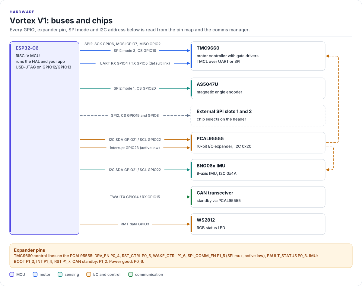
Figure description and sources
The ESP32-C6 on the left runs all the software. Each arrow to the right is one bus or signal, labelled with the GPIOs it uses: SPI2 to the TMC9660 motor controller and the AS5047U encoder (plus two external chip selects), a UART that is the TMC9660's default host link, I2C to the PCAL95555 I/O expander and the BNO08x IMU, TWAI to the CAN transceiver, and one data line to the WS2812 status LED. The PCAL95555 drives the TMC9660 control lines (driver enable, reset, wake, SPI mux) and the IMU's boot and reset lines, and reads their fault and interrupt outputs. The layout is drawn by hand; every GPIO number, expander bit, chip select, SPI mode and I2C address is read from the functional pin map and the comms manager, so a pin change rebuilds this figure.
Drawn from: lib/core/hf-core-drivers/internal/hf-pincfg/src/hf_functional_pin_config_vortex_v1.hpp HF_FUNCTIONAL_GPIO_PIN_LIST; lib/managers/CommChannelsManager.h SpiDeviceId; lib/managers/CommChannelsManager.cpp add_builtin_device; figure module docs/diagrams/figures/board-overview.py.
The chips
| Chip | What it does | Bus | Manager that owns it |
|---|---|---|---|
| ESP32-C6 | RISC-V MCU with Wi-Fi 6, BLE, 802.15.4 and TWAI (CAN); runs the HAL and your application | - | all of them |
| TMC9660 | Motor controller with integrated gate drivers and its own FOC current, velocity and position loops; also provides GPIO, ADC channels and a chip temperature | UART (default) or SPI2 | MotorController |
| AS5047U | 14-bit magnetic angle encoder | SPI2 | EncoderManager |
| BNO08x | 9-axis IMU with on-chip sensor fusion | I2C | ImuManager |
| PCAL95555 | 16-bit I2C I/O expander: TMC9660 control lines, IMU boot/reset, CAN standby, power good | I2C | GpioManager |
| NTC thermistor | Board temperature, read on TMC9660 input AIN3 | through the TMC9660 | TemperatureManager |
| CAN transceiver | Physical layer for the TWAI controller | TWAI | CommChannelsManager |
| WS2812 | RGB status LED | RMT data line | LedManager |
Things to know before you wire anything
- The TMC9660 has two host links. The UART is always connected. SPI2 reaches the TMC9660 only while the
expander pin
PCAL_TMC_SPI_COMM_EN(active low) selects it, because the same SPI2 lines also serve the AS5047U and the external slots. The HAL uses the UART unless you callVortex::SetOnboardTmc9660Transport(VortexOnboardTmc9660Transport::Spi)beforeEnsureInitialized(). - TMC9660 GPIO17 and GPIO18 appear twice in the pin map: as expander inputs (
PCAL_TMC_GPIO17_EXP_IN,PCAL_TMC_GPIO18_EXP_IN) and as TMC9660 GPIOs (TMC_GPIO17,TMC_GPIO18). Both views see the same nets. - There is no encoder fitted by default. The AS5047U chip select is wired, but
EncoderManagercreates no device until you callCreateAs5047uDevice(). - Do not copy pin numbers from TMC9660 evaluation-kit examples. Use the pin map.
Bench documents
The bring-up notes written on the bench live next to the examples, not on this site: bench matrix, BLDC bring-up and the example docs index.