Porting
Run the driver on a new MCU by writing one class with one method, the SPI transfer, and optionally a delay.
The driver never calls your SDK directly. It calls transfer() on a class you derive from
at25040::SpiInterface<Self> (in inc/at25040_spi_interface.hpp). The base
class uses CRTP: the call is resolved at compile time, so there are no virtual functions, no vtable and nothing to
allocate.
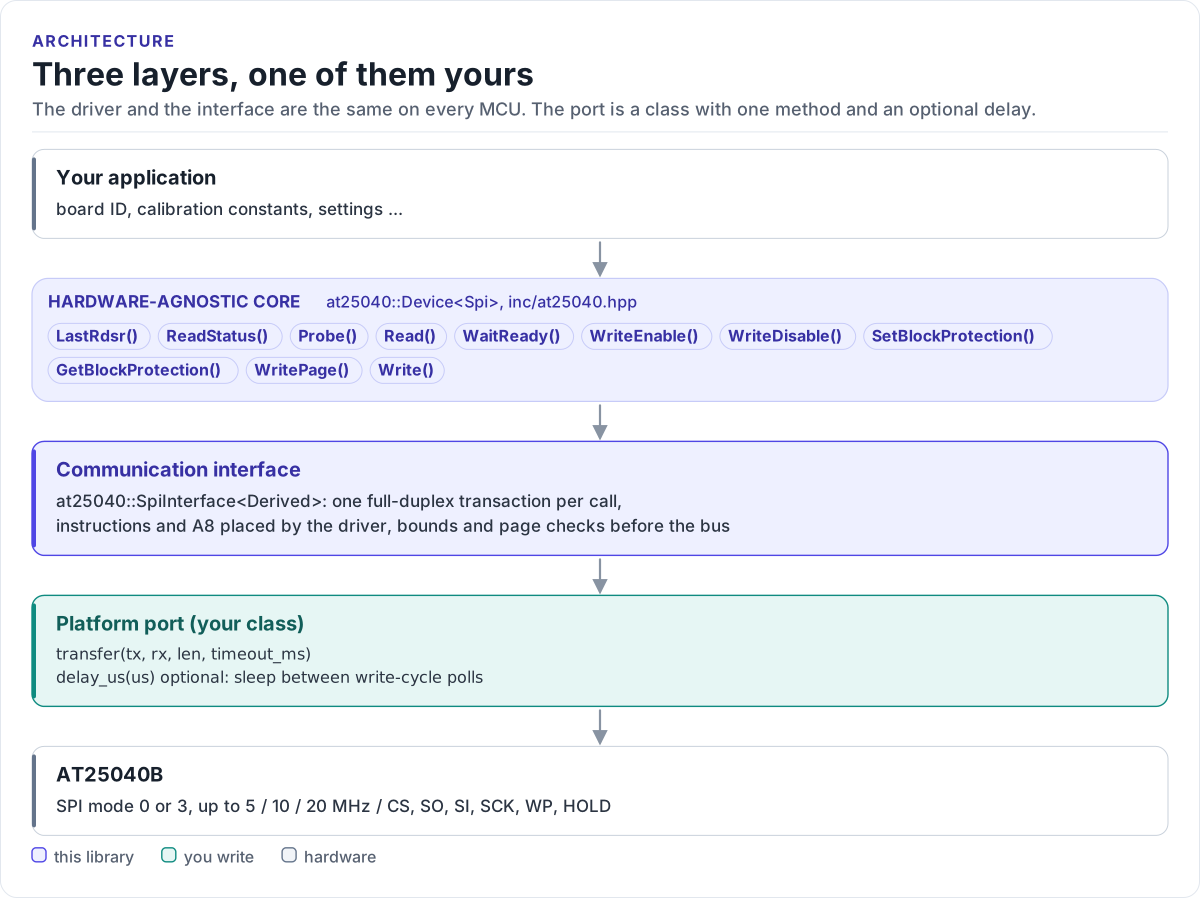
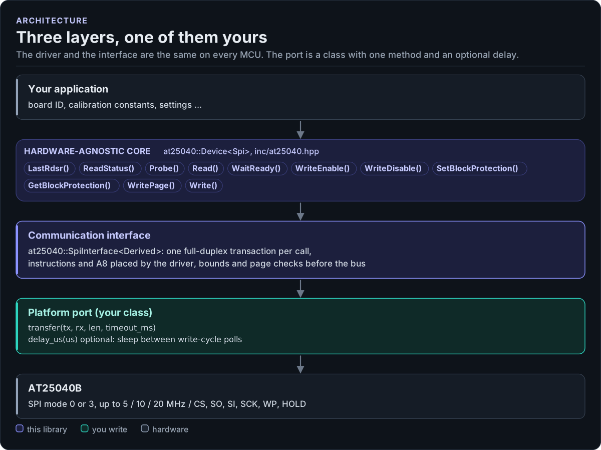
Figure description and sources
From top to bottom. Your application talks to one at25040::Device
Drawn from: inc/at25040.hpp Device members; inc/at25040_spi_interface.hpp SpiInterface; figure module docs/diagrams/figures/driver-layers.py.
What you implement
| Argument | Contract |
|---|---|
tx, len |
Send len bytes in one transaction, CS low for all of them |
rx |
Receive len bytes: rx[i] is the byte clocked in while tx[i] went out |
timeout_ms |
Give up after this long and return false |
| return | true when the transaction completed, false on a bus error or timeout |
The driver always passes rx of the same length as tx (at most 18 bytes) and timeout_ms = 20.
SPI port
#include "at25040_spi_interface.hpp"

class MySpi : public at25040::SpiInterface<MySpi> {
public:
  // One transaction: CS low, `len` bytes full duplex (SPI mode 0 or 3, MSB first), CS high.
  // rx[i] is the byte clocked in while tx[i] went out. Return false only on a bus error or timeout.
  bool transfer(const uint8_t* tx, uint8_t* rx, std::size_t len, uint32_t timeout_ms) noexcept {
    return platform_spi_transfer(tx, rx, len, timeout_ms);
  }

  // Optional: sleep at least `us` microseconds. With it, WaitReady() (and every write) sleeps 100
  // us between status polls; without it, the driver polls back to back for a bounded count.
  void delay_us(uint32_t us) noexcept {
    platform_delay_us(us);
  }
};
Rules the transfer must follow:
- SPI mode 0 or 3, MSB first, no faster than the chip allows at your VCC: 20 MHz at 4.5 V, 10 MHz at 2.5 V, 5 MHz at 1.8 V.
- One transaction per call. CS goes low before the first byte and high after the last; never split a call into two CS periods, never merge two calls. The chip starts a write cycle on the CS rising edge after WRITE.
- Full duplex. Fill
rxwith what came back on MISO;Probe()andRead()read their results from it. - Return
falseonly for a bus failure. A missing chip is the driver's job: it shows up as0xFFbytes.
Optional delay hook
The driver detects this member at compile time. With it, WaitReady() (and so every write) sleeps 100 µs between
status polls; an RTOS port can yield there. Without it, the driver polls back to back for a bounded number of polls
(kPollsPerMsWithoutDelay per millisecond of budget) that lasts at least the budget even at 20 MHz, so a write
still waits for its write cycle, but keeps the bus busy while it does.
Chip select and shared buses
Drive CS from the SPI peripheral (ESP-IDF spics_io_num, STM32 hardware NSS) or toggle a GPIO around the transfer.
On a shared bus, take the bus lock for the whole transfer() so another device cannot get between CS low and CS
high. Keep tCSS, tCSH and tCS at 100 ns or more (200 ns at 1.8 V).
Reference implementation
The ESP32 example's port in
at25040_esp32_example.cpp is a complete ESP-IDF spi_master
port: one spi_transaction_t with length = len * 8, tx_buffer = tx and rx_buffer = rx, sent with
spi_device_polling_transmit() on a device configured for mode 0 with CS on spics_io_num, and delay_us() on
esp_rom_delay_us(). It does not use the ESP-IDF command or address phases: the driver puts the opcode (with A8 in
bit 3) in tx[0] and the address byte in tx[1].
Check your port
- Build it: the port on this page is compiled by the host CI from
tests/docs/, with the driver instantiated over it. - Call
Probe()and logLastRdsr(). A ready AT25040B with no protection reads0x00;0xFFmeans nothing answered. - Write one page (
WritePage()waits for the write cycle), read it back. - Read across
0x0FF/0x100in two calls to prove A8 reaches the chip: the two halves must hold different data.
Threads
The driver is not thread-safe. Give each EEPROM one owner task, or guard every call on a driver object (and its
port) with one mutex. On a shared bus, the bus lock in transfer() is not enough for a write followed by a status
poll; hold the mutex for the whole sequence.