Architecture
How the driver is put together: three layers, what each owns, and how one call reaches the chip.
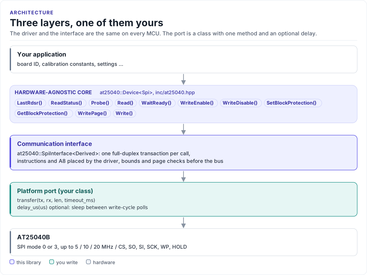
Figure description and sources
From top to bottom. Your application talks to one at25040::Device
Drawn from: inc/at25040.hpp Device members; inc/at25040_spi_interface.hpp SpiInterface; figure module docs/diagrams/figures/driver-layers.py.
The three layers
| Layer | Where | You change it |
|---|---|---|
Hardware-agnostic core: Device<Spi>, uses only the port's transfer() |
inc/at25040.hpp, inc/at25040_registers.hpp |
Never, for a new board |
Communication interface: SpiInterface<Derived>, one method |
inc/at25040_spi_interface.hpp |
Never |
| Platform port: your class, on your SDK | Your project | Once per MCU or board (Porting) |
Everything above the port is the same on ESP32, STM32, a Linux host or the unit-test model. That is how the host tests run the real driver code without hardware.
How one call reaches the chip
sequenceDiagram
    participant A as Application
    participant D as Device
    participant P as Your port
    participant E as AT25040B
    A->>D: WritePage(0x110, data, 4)
    D->>D: check pointer, length, page and range
    D->>P: transfer([0x06], 1 byte)
    P->>E: WREN
    D->>P: transfer([0x0A, 0x10, d0..d3], 6 bytes)
    P->>E: WRITE, A8 in the opcode
    P-->>D: true
    loop until RDY = 0 (at most 10 ms)
        D->>P: transfer([0x05, 0x00], 2 bytes)
        P->>E: RDSR
        D->>P: delay_us(100), if the port has it
    end
    D-->>A: Status::Ok (write cycle finished)
Each transfer() is one CS-low period, and the driver passes a 20 ms timeout to every transfer. Reads and status
calls are one transfer per 16 data bytes; writes add the status polls of the write cycle.
Why CRTP
The interface is a class template parameter, not a virtual base class. The compiler sees your port's transfer()
(and delay_us(), if it has one, detected at compile time) directly and inlines it; the driver has no vtable,
allocates nothing and needs no RTTI. The cost is that the driver type names the port: Device<MySpi>. Code that has
to work with several port types takes the driver as a template parameter too.
Bounded waits, no hidden state
The driver keeps one byte of state: the last status register value (LastRdsr()). It does not track the write
cycle, the write-enable latch or the protection level; the chip does, and ReadStatus() reads them. The only wait
is the write cycle: a write returns when RDSR shows the chip ready again, or with Timeout after
kWriteCycleTimeoutMs (10 ms).
Source map
| Path | Contents |
|---|---|
inc/at25040.hpp |
Device<Spi>, Status, GetAt25040DriverVersion() |
inc/at25040_registers.hpp |
Opcodes, status bits, capacity and page size |
inc/at25040_spi_interface.hpp |
SpiInterface<Derived>, the CRTP contract |
inc/at25040_version.h.in |
Version header template, filled in by CMake |
tests/ |
Host unit tests, the chip model and the compiled documentation snippets |
examples/esp32/ |
ESP-IDF application |