Modbus-RTU protocol
The frames the driver sends, the registers behind each call, and how values are scaled, from the operation manual's register tables.
Function codes
The BASIS-2 implements three Modbus functions, and the driver uses all three.
| Code | Name | Driver | Reply |
|---|---|---|---|
0x03 |
Read holding registers | ReadHoldingRegisters(), every read call |
Address, 0x03, byte count, data, CRC |
0x06 |
Write single register | WriteSingleRegister(), every 16-bit write |
An echo of the request |
0x10 |
Write multiple registers | WriteMultipleRegisters(), the 32-bit writes |
Address, 0x10, start register, count, CRC |
A rejected request gets an exception reply: the function code with bit 7 set (0x83, 0x86, 0x90), an
exception code and the CRC, 5 bytes in all (Modbus Application Protocol V1.1b3, section 7). The driver reads the
first 3 bytes of every reply; when bit 7 is set it reads the 2 CRC bytes, checks the CRC and returns
ModbusException without waiting for the timeout. GetLastException() returns the exception code:
| Code | ModbusExceptionCode |
Typical cause on a BASIS-2 |
|---|---|---|
0x01 |
IllegalFunction |
A function other than 03, 06, 16 |
0x02 |
IllegalDataAddress |
The manual's "Bad Address": a register this model or firmware does not have |
0x03 |
IllegalDataValue |
A value or register count the instrument does not accept |
0x04 |
ServerDeviceFailure |
An error inside the instrument |
The write-single echo carries the value the host sent, not the value the instrument stored: an out-of-range setpoint is adjusted inside the instrument but echoed unchanged. Read the register back when you need the stored value. Reading an undefined register may return 0 or an exception.
Frame format
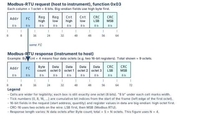
| Field | Size (bytes) | Notes |
|---|---|---|
| Address | 1 | 1 to 247; 0 is broadcast (writes only, no reply) |
| Function | 1 | 0x03, 0x06, 0x10; bit 7 set in an exception reply |
| Data | 1 to 69 | Big-endian register addresses, counts and values |
| CRC-16 | 2 | Polynomial 0xA001 (reflected 0x8005), initial value 0xFFFF, low byte first |
The driver sends the data addresses of the manual's tables unchanged: register 2100 is 0x0834 in the request.
The driver reads at most 32 registers and writes at most 32 in one request (its buffer sizes).
Instantaneous data (2053 to 2109)
| Register | Contents | Scaling | Field |
|---|---|---|---|
| 2053-2054 (R/W) | Commanded setpoint, signed 32-bit; takes effect when 2054 is written | value / 1000 | SetSetpoint() |
| 2100 (R/W) | Selected gas number | Gas |
gas, SetGas() |
| 2101 (R) | Status: +1 MOV, +2 TOV, +4 OVR, +8 HLD, +16 VTM |
bits | *_overrange, valve_held, valve_thermal_management |
| 2102 (R) | Temperature, signed | value / 100 = °C | temperature_c |
| 2103 (R) | Flow, signed 16-bit | factory-set decimals | flow |
| 2104-2105 (R) | Total volume since power-up or reset | factory-set decimals | total_volume |
| 2106 (R) | Current setpoint (may lag the command while ramping) | setpoint |
|
| 2107 (R) | Valve drive | value / 100 = % | valve_drive_pct |
| 2108-2109 (R) | Batch volume remaining | as 2104-2105 | batch_remaining |
ReadInstantaneous(decimals) reads 2100 to 2109 in one request and divides flow, total, setpoint and batch by
10decimals. The manual says these registers carry a "factory-set number of decimal places" but names
no register that reports it; take it from the instrument's calibration sheet or compare with the ASCII data frame.
The setpoint write is always value / 1000, whatever the decimals.
Measurement window (4200 to 4214)
| Register | Contents |
|---|---|
| 4200 (R/W) | Trigger (controllers): +1 on a digital setpoint change, +2 on a valve-hold change, +4 when the low register of the previous average flow (4215) is read |
| 4201 (R/W) | Samples to take, about 2.5 ms each; a write starts a new window |
| 4202, 4203 (R) | Minimum and maximum temperature, value / 100 = °C |
| 4204, 4205 (R) | Minimum and maximum flow, signed 16-bit, factory-set decimals |
| 4206 (R) | Samples averaged so far |
| 4207, 4208 (R) | Average temperature and average flow |
| 4209 (R) | Valve drive, value / 100 = % |
| 4210 to 4213 (R) | Previous window: minimum and maximum flow, samples, average temperature |
| 4214-4215 (R) | Previous window's average flow, signed 32-bit, high register first |
StartMeasurementSamples() writes 4201, ConfigureMeasurementTrigger() writes 4200 and ReadMeasurement()
reads 4201 to 4215 in one request. The manual gives the previous average flow as a 4-byte integer at 4214, so it
fills 4214 and 4215 like every other 32-bit value; prev_avg_flow_raw is decoded from both.
num_samples_collected is 4206 (samples averaged so far), num_samples_requested is 4201.
Configuration and function registers
| Register | Contents | Driver |
|---|---|---|
| 21 (R/W) | Baud rate code: 0 = 4800, 1 = 9600, 2 = 19200, 3 = 38400, 4 = 57600, 5 = 115200 | SetBaudRate() |
| 25 (R) | Firmware version: Va.b.c = 256a + 16b + c | ReadIdentity() |
| 26-31 (R) | Serial number, two characters per register | ReadIdentity() |
| 35-36 (R) | Full scale in SCCM, unsigned 32-bit | reg::FullScaleFlowSccm |
| 39 (W) | Tare: write 0xAA55 |
Tare() |
| 45 (R/W) | Modbus address, 1 to 247 | SetModbusAddress() |
| 46 (R/W) | ASCII unit ID, A to Z |
SetAsciiUnitId() |
| 47-48 (R) | Full scale in the flow units, value / 1000 | ReadIdentity() |
| 49 (R) | Flow units code, 0 = SCCM to 19 = SCFD | FlowUnits |
| 51 (R/W) | Samples per tare, 1 to 65535 | reg::TareSampleCount |
| 52 (R/W) | Reference temperature, 0 to 3000 = 0 °C to 30 °C | SetReferenceTemperatureC() |
| 53 (W) | Reset the totalizer (and the batch): write 0xAA55 |
ResetTotalizer() |
| 54 (R/W) | Totalizer limit mode, 0 to 3 | SetTotalizerLimitMode() |
| 55 (R/W) | Flow averaging time constant, 0 to 2500 ms | SetFlowAveragingMs() |
| 56 (R/W) | Command protocol: 0 = BASIS 2, 1 = BASIS 1 | reg::CommandProtocol |
| 80 (W) | Factory restore: write 0x5214 |
FactoryRestore() |
| 81-140 (R) | Gas table: 12 entries of number, k factor (4096 = 1.0), label | reg::GasInfoTableStart |
Control registers (controllers only)
| Register | Contents | Driver |
|---|---|---|
| 514 (R/W) | Communication watchdog, 0 to 5000 ms, 0 = off | SetCommWatchdogMs() |
| 515 (R/W) | Autotare: 1 on, 0 off | SetAutotareEnabled() |
| 516 (R/W) | Setpoint source: 0 analog, 1 digital saved, 2 digital unsaved | SetSetpointSource() |
| 519, 520 (R/W) | P and I gain of the PDF loop, 0 to 65535 | reg::PgainPdf, reg::IgainPdf |
| 521-522 (R/W) | Batch volume, in the total-volume units and scaling | SetTotalizerBatch() |
| 524-525 (R/W) | Maximum setpoint ramp, % of full scale per ms × 107; 0 = no ramp | SetMaxSetpointRamp() |
Several registers were added in later firmware (2053 in V2.1.0, address and unit ID in V2.4.0, most data registers in V3.0.0, the gas table in V3.0.5). Read register 25 first when an older instrument answers with an exception.
Magic values
| Value | Register | Effect |
|---|---|---|
0xAA55 (43605) |
39 | Tare; interrupts a running measurement |
0xAA55 (43605) |
53 | Totalizer and batch reset |
0x5214 (21012) |
80 | Factory restore; power-cycle afterwards |
The ASCII protocol
The instrument also accepts Alicat's ASCII commands (A for the data frame, AS 15.44 for a setpoint), addressed
by the unit ID. The driver does not implement them; the manual lists them.
Switching register 56 to BASIS 1 changes the command set and works only with SCCM, SLPM, NCCM and NLPM.