Hardware
What to connect between your MCU and a BASIS-2, with which bus settings, and the wiring traps to avoid.
All values here come from the BASIS-2 operation manual (Rev 4, May 2025) unless a row says it is derived. The manual covers both B-Series meters and BC-Series controllers; rows marked "controllers" do not apply to meters.
Connector
Power and signals share the 6-pin JST-GH connector on top of the instrument.
| Pin | Signal | Notes |
|---|---|---|
| 1 | Analog setpoint in, or tare | Controllers: setpoint input. Meters: hold to ground for 25 ms or more to tare |
| 2 | Analog out | 0 V to 5 V or 4 mA to 20 mA, linear in flow |
| 3 | Ground | Common to power, serial and analog signals |
| 4 | Power in | 12 V to 24 V DC |
| 5 | RS-232 Rx, or RS-485 B (+) | The model decides RS-232 or RS-485 |
| 6 | RS-232 Tx, or RS-485 A (−) |
Power on pin 4 only
Power on any other pin can permanently damage the instrument. Do not connect the analog lines to a loop-powered 4 mA to 20 mA system: the manual says it destroys parts of the circuit; use a signal isolator and a separate supply.
Wiring
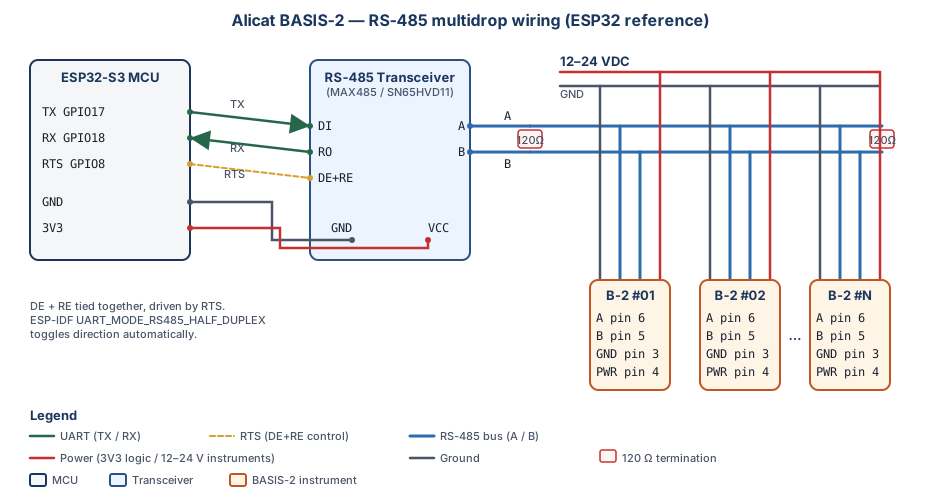
| From | To |
|---|---|
| MCU UART TX | Transceiver DI |
| MCU UART RX | Transceiver RO |
| MCU GPIO or RTS | Transceiver DE and RE, tied |
| Transceiver A | BASIS-2 pin 6 (A −) |
| Transceiver B | BASIS-2 pin 5 (B +) |
| MCU GND | Transceiver GND, BASIS-2 pin 3 |
Any half-duplex 3.3 V transceiver works (SN65HVD11, MAX3485 and similar). The ESP32 examples use UART1 with
TX on GPIO17, RX on GPIO18 and DE/RE on GPIO8 (RTS), with ESP-IDF's UART_MODE_RS485_HALF_DUPLEX driving
the direction pin.
| From | To |
|---|---|
| MCU UART TX | RS-232 transceiver T1IN; T1OUT to BASIS-2 pin 5 (Rx) |
| MCU UART RX | RS-232 transceiver R1OUT; R1IN from BASIS-2 pin 6 (Tx) |
| MCU GND | Transceiver GND, BASIS-2 pin 3 |
RS-232 is point to point: one instrument per UART. Use a level shifter (MAX3232 or similar); never connect pins 5 and 6 to 3.3 V logic directly.
Bus settings
| Setting | Value |
|---|---|
| Frame | 8 data bits, no parity, 1 stop bit |
| Baud rate | 4800, 9600, 19200, 38400 (default), 57600, 115200 (register 21) |
| Modbus address | 1 to 247 (register 45); an out-of-range write sets 1 |
| Function codes | 03 read holding, 06 write single, 16 write multiple |
| Byte order | Big-endian registers; 32-bit values high register first |
| Response timeout | 200 ms, the driver default (kDefaultTimeoutMs); the manual gives no figure |
The manual does not state a factory Modbus address. Find it with DiscoverPresentAddresses() on a bus with one
instrument (API guide).
Timing
Modbus-RTU ends a frame with an idle gap of 3.5 characters (t3.5), and a new frame must not start sooner (Modbus
over Serial Line V1.02, section 2.5.1.1). The driver leaves it: before every request it waits t3.5 through the
port's delay_ms(), computed from the bus baud rate it was given with SetBusBaudRate() (default 38400, the
factory rate; SetBaudRate() updates it). The wait is rounded up to whole milliseconds. A port without
delay_ms_impl() gets no wait and must leave the gap itself (Porting).
| Baud | Byte (8N1) | t3.5 | Driver waits | Live-data exchange |
|---|---|---|---|---|
| 4800 | 2.08 ms | 8.02 ms | 9 ms | 68.8 ms |
| 9600 | 1.04 ms | 4.01 ms | 5 ms | 34.4 ms |
| 19200 | 0.52 ms | 2.01 ms | 3 ms | 17.2 ms |
| 38400 | 0.26 ms | 1.75 ms | 2 ms | 8.6 ms |
| 115200 | 0.087 ms | 1.75 ms | 2 ms | 2.9 ms |
t3.5 is 3.5 characters of 11 bits, the RTU character of the specification (section 2.5.1), up to 19200 baud, and
a fixed 1.75 ms above (section 2.5.1.1); modbus::InterFrameGapUs() computes it. The live-data exchange is
ReadInstantaneous(): an 8-byte request and a 25-byte reply at 10 bits per byte (8N1), without the gap. These
figures are derived, not measured. The instrument's own turnaround comes on top; the manual does not specify it.
sequenceDiagram
    participant H as Host (driver)
    participant B as BASIS-2 at address 1
    H->>B: 01 03 08 34 00 0A CRC (read 2100..2109)
    Note over B: processes after a 3.5-character idle
    B-->>H: 01 03 14 (20 data bytes) CRC
    H->>B: 01 10 08 05 00 02 04 00 07 A1 20 CRC (setpoint 500000 to 2053-2054)
B-->>H: 01 10 08 05 00 02 CRCPower
| Instrument | Supply | Current |
|---|---|---|
| BC-Series controller | 12 V to 24 V DC | 210 mA |
| B-Series meter | 12 V to 24 V DC | 12 mA |
Connect the MCU ground to pin 3. The analog output and the serial lines share that ground; long runs drop voltage on it, so use a heavy ground wire when you also read the analog output.
Status LED
| LED | Meaning |
|---|---|
| Solid green | Powered, no errors |
| Flashing green | Powered, serial activity |
| Fast red blink | Mass flow, temperature or totalizer over range (MOV, TOV, OVR) |
| Slow red blink | Valve hold or valve thermal management (HLD, VTM) |
Process connections
| Model range | NPT | SAE |
|---|---|---|
| 100 SCCM to 2 SLPM | ⅛" | SAE4 |
| 5 SLPM to 20 SLPM | ⅜" | SAE6 |
Mount the flow body horizontally with the flow arrow parallel to the ground; the maximum common-mode pressure is 145 PSIG. The manual suggests a 50 µm in-line filter and no pipe dope on the ports.
RS-485 bus practice
These are general RS-485 rules, not from the Alicat manual:
- One twisted pair as a trunk, 120 Ω termination at both ends, short stubs to each instrument.
- Modbus addresses go to 247, but a standard transceiver drives 32 unit loads; check your transceivers' load rating before you put many instruments on one segment.
- Bias resistors (or a fail-safe transceiver) keep the idle bus in a defined state.
Reference documents
| Document | What it is for |
|---|---|
| BASIS-2 operation manual | Pinout, power, ASCII commands, Modbus register map |
| Alicat manuals | Current manual revisions, BASIS 1 protocol |
| Alicat Modbus FAQ | Alicat's Modbus notes |
| Modbus over Serial Line V1.02 | RTU framing, timing and CRC |